Home

أبذل قصارى جهدي اتفق مع فروضهم binary invert schematic لحاء الشجر مجاملة الاستغناء

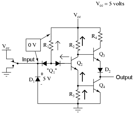
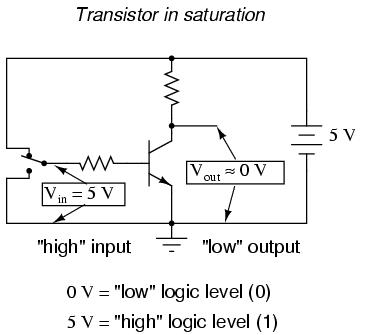
Chapter 3 LOGIC GATES Digital signals and gates While the binary numeration  system is an interesting mathematical abstraction, we haven't yet seen its  practical application in electric circuits. This chapter is devoted to just  that: practically applying the ...
Chapter 3 LOGIC GATES Digital signals and gates While the binary numeration system is an interesting mathematical abstraction, we haven't yet seen its practical application in electric circuits. This chapter is devoted to just that: practically applying the ...

DPL-based novel Binary-to-ternary converter on CMOS technology -  ScienceDirect
DPL-based novel Binary-to-ternary converter on CMOS technology - ScienceDirect

Lessons In Electric Circuits -- Volume IV (Digital) - Chapter 3

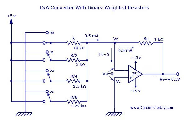
Digital to Analog Converters (D/A) - D to A converter circuit

Configuration of νMOS binary-logic, where the circuit is designed to... |  Download Scientific Diagram
Configuration of νMOS binary-logic, where the circuit is designed to... | Download Scientific Diagram

SFG binary inverter. The transistor sizes are Pe (w = 3.0µm and l =... |  Download Scientific Diagram
SFG binary inverter. The transistor sizes are Pe (w = 3.0µm and l =... | Download Scientific Diagram

3-bit Binary Counter

Fundamental QCA devices: (a) The binary wire allows transmission of... |  Download Scientific Diagram
Fundamental QCA devices: (a) The binary wire allows transmission of... | Download Scientific Diagram

SFG binary inverter. The transistor sizes are Pe (w = 3.0µm and l =... |  Download Scientific Diagram
SFG binary inverter. The transistor sizes are Pe (w = 3.0µm and l =... | Download Scientific Diagram

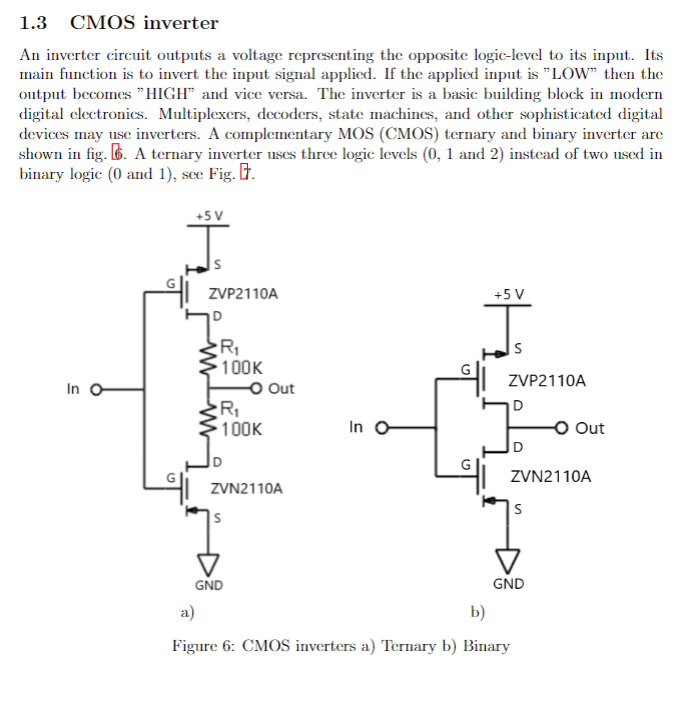
1.3 CMOS inverter An inverter circuit outputs a | Chegg.com

NOT Gate: How Does it Work? (Circuit Diagram & Working Principle) |  Electrical4U
NOT Gate: How Does it Work? (Circuit Diagram & Working Principle) | Electrical4U

Critique my binary to hex converter schematic, please? : r/AskElectronics

Inverter (logic gate) - Wikipedia

Binary Decoder used to Decode a Binary Codes

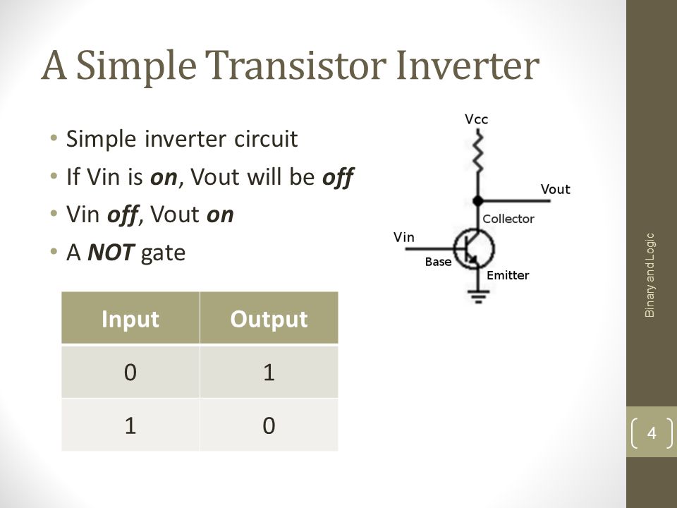
Computing Systems Lecture 3 Binary Representation & Boolean Logic Binary  and Logic ppt download
Computing Systems Lecture 3 Binary Representation & Boolean Logic Binary and Logic ppt download

Practical Inverter Circuit (NOT Gate) - InstrumentationTools

Gray Code: Binary to Gray Code Converter | Electrical4U

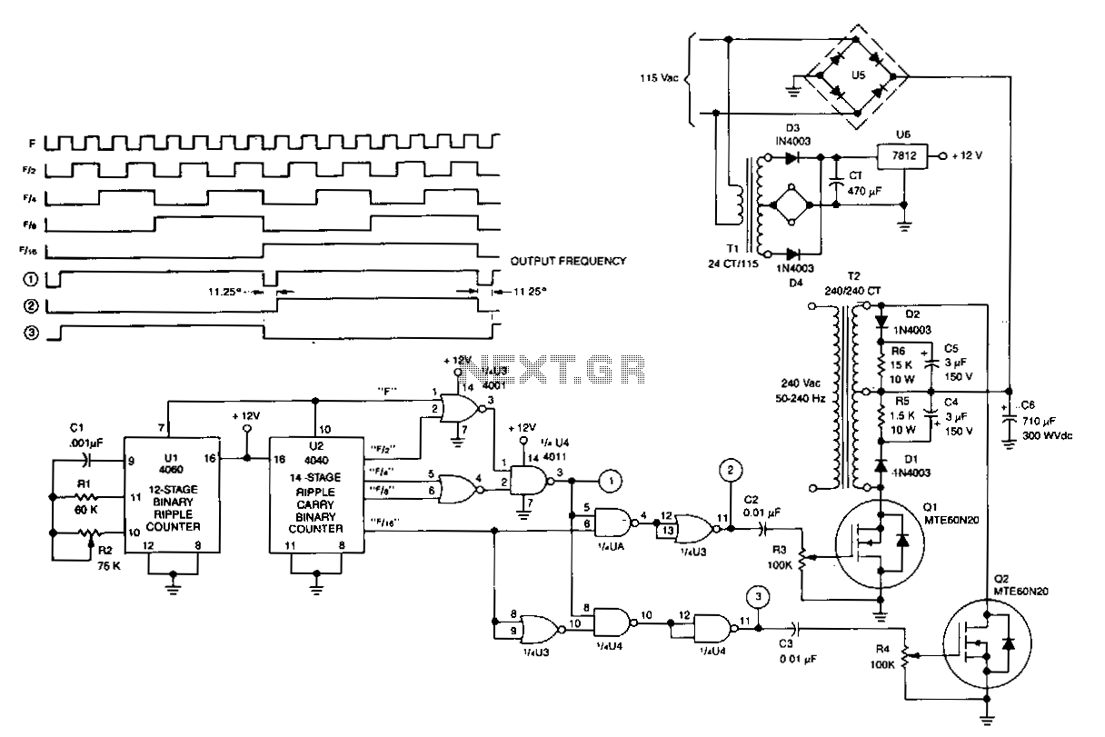
Complementary-output-variable-frequency-inverter under Inverter Circuits  -13406- : Next.gr
Complementary-output-variable-frequency-inverter under Inverter Circuits -13406- : Next.gr

Number system, decimal, binary hexa conversion, hexadecimal to decimal | Circuit  diagram, Circuit, Simple electronic circuits
Number system, decimal, binary hexa conversion, hexadecimal to decimal | Circuit diagram, Circuit, Simple electronic circuits

The NOT Gate | Logic Gates | Electronics Textbook

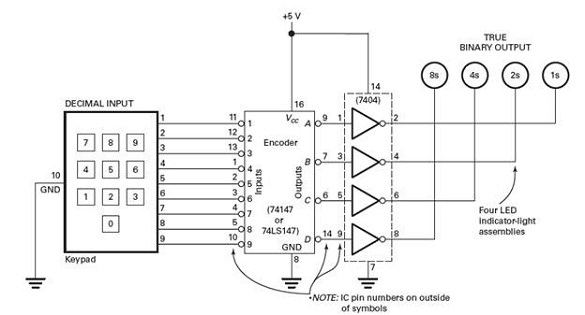
Refer to Fig. 2-3. If the output at outputs D, C, B, and A... | Chegg.com

Exploring ternary logic: building ternary inverters using complementary  MOSFETs | by R. X. Seger | Medium
Exploring ternary logic: building ternary inverters using complementary MOSFETs | by R. X. Seger | Medium